TMV Temperature Monitor + Regulation

Two complementary elements in transformer monitoring are temperature and voltage regulation. For smaller transformers, in which simplified monitoring is acceptable and even desirable.The TMV meets these two needs both working as temperature monitor and voltage regulator. This combines the functions of the TML and IDV, functionality performed by just one device.
Based on measurements and engineering algorithms, the TMV issues alarmsthrough a colour code system in the event of abnormalities and advance maintenance reminders, as programmed by the user. This facilitates the user to rapidly check the status of the disconnect switch.
- Green Transformer is working correctly. No maintenance is needed;
- Blue Transformer is working correctly. Maintenance reminder;
- Yellow Minor abnormality;
- Red Major abnormality.
Transformer statuses can be allocated to TMV output contacts, thus providing remote state indication of successful or abnormal operation.
The TMV Temperature Monitor + Regulator has a series of useful features, as listed below:
Functionality
- Measurement of two temperatures such as ambient, transformer oil or OLTC oil;
- Temperature supervision and thermal protection of up to three windings.
- Calculation of the final gradient prediction of oil-winding temperature for the current load
- Oil temperature redundant measurement capability, avoiding unavailability of the measurement in case of sensor Pt100 failure.
- Local control of the Automatic or Manual cooling via front buttons or remotely through communication port.
- Pre-cooling function to increase the service life of the insulation under high loads.Extends the service life of the insulation by activating the cooling groups when load levels configured are reached. Taking advantage of the large thermal inertia of the oil, forced cooling is turned on before the temperature increases, reducing the exposure of the windings to high temperatures and limiting loss of insulation service life. The user can program:
– Loading percentage to activate any stage of the forced cooling.
– Hysteresis to turn off forced cooling stages when loading reduces.
- Automatic forced cooling grouprotation, offering uniform use of the fans and pumps
- Cooling Exercise Function to prevent failure in fans and pumps. The Cooling Exercise function obviates lack of fan and/or pump activity for long periods in low load transformers or during periods in which ambient temperature is low. This prevents the shafts from blocking due to dirt or dry grease build-up. The internal clock of the equipment activates the cooling equipment daily as configured:
– Hour and minute for start of cooling operation.
– Total daily fan operation time, from 0 to 999 minutes.
The cooling exercise function can also facilitate pre-cooling in transformers that are subject to cyclic loading; the cooling start-up should be configured for a time prior to the daily load peak.
- Line Drop Compensation by Resistance or Reactance (Rx) adjustments or through the simplified voltage drop percentage method
- Use of the Master-Slave or Circulating Current methods for Parallel control of up to three transformers;
- Local/Remote and Manual/Automatic OLTC control.
- OLTC blocking in the event of overcurrent and undervoltage. Selection of blocking the OLTC or quick voltage reduction actuation if overvoltage occurs options.
- Automatic blocking of a false operation of the OTLC;
- VT/CT angle adjustable from 0 to 330deg, facilitating all connection options for the VT / CT connections;
- Multi-measurement Function: display of voltages in the transformer and the load; voltage deviations; current; active, reactive and apparent power; power factor and frequency;
- Self-Diagnostic for the detection of internal failures or sensor and wiring problems.
- Insulation Aging Monitor. This function monitors loss of service life of the winding online, making important information available for the diagnosis and prognosis of the equipment status:
-Current percentage of remaining service life, from 100% (new insulation) to 0% (end of insulation service life);
-Average loss of insulation life, in % per day, calculated over a period of time chosen by the user;
-Extrapolation of the remaining service life of the insulation, calculated as a function of the aforementioned variables (remaining life percentage and average loss of life rate).
- OLTC Temperature Differential. This function allows the user to compare the transformer oil temperature to the OLTC temperature. Abnormal temperature differentials are detected and maintenance crews can be alerted for OLTC failures that may develop. As the temperature differential is subject to the influence of external variables, monitoring is done in two different ways facilitating effective diagnosis and preventing false alarms:
-Instantaneous Differential Monitoring – Offers fast alarm response in the event of highly intensity failures even if they are unsustained;
-Filtered Differential Monitoring – Passing the instantaneous differential through a low-pass filter detects evolution trends of the differential. This indicates permanent low intensity failures, the detection time is longer.
- OLTC Maintenance Assistant. OLTC position is determined based on the position input, then:
-OLTC operation counter, with maintenance reminder based on number of operations;
-Integration of switching current squared, with a reminder of maintenance due based on high I squared sum total.
-Forecast of the remaining time before the next OLTC maintenance.
-Maintenance warnings, thresholds configured in advance.
- GPRS Cellular Modem Communication. Communication through a GPRS Cellular Modem inside the TML.
- Auxiliary Voltage Transformers. An auxiliary VT must be used if the OLTC motor is supplied from an AC voltage higher than 265 Vac or for isolation of the motor voltage from control voltage.
- PT100Ω temperature sensor at 0ºC are supplied based on application requirements.
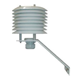
- Weather Shield for Pt100 Ambient Temperature Sensor supplied based on application requirements.
Physical Characteristics
- IED (Intelligent Electronic Device) specifically developed for the substation outdoor conditions(interference, extreme temperatures);
- Rugged construction, exceeding the required EMC standards, to operate in severe electromagnetic conditions and with an operating temperature of -20 to 70degC or -40 to 85degC;
- Total absence of mechanical parts that might require configuration and calibration.
- Compact size, space saving reducing panel costs;
- High brightness VFD (Vacuum Fluorescent Display), readable under any lighting and temperature conditions;
- Internal clock lasting 48 hours without power supply, without batteries;
- Non-volatile mass memory for measurements and alarms, eliminating the need for maintenance; Interval between recordings set by the user as well as the temperature variation for recording.
- Universal power supply of 38~265 Vac/ 38~275 Vdc, 50/60Hz.
Inputs
- One input for voltage:
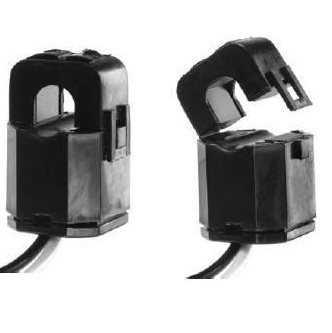
- Three inputs to measure true-rms AC current from external clip-on split core window typeCT’s;External clip-on CTs with a split core are required for the operation of the TMV.
- Two inputs to measure temperature using RTD PT100Ω sensors with self-calibration, guaranteeing high accuracy and stability over the entire ambient temperature range;
- Two remote control dry input contacts, for change of regulation settings, regulation groups, paralleling control and other functions;
- One input for potentiometric position transmitter, which facilitates OLTC tap position measurement;This is an input to measure the position of the OLTC with a potentiometric transmitter with compensation for cable resistance and error detection. Associated functions:
-Current output programming for TAP remote indication ;
-OLTC local manual command (front panel) and through serial communication;
-Restriction of the OLTC course range (minimum and maximum TAPs allowed) and memory of the maximum and minimum positions reached since the last reset;
-Protection against improper OLTC operation: OLTC is blocked if operations that were not initiated by the TMV are performed.
Outputs
- 14 signalling relays with programmable functions and type of operation (NO/NC) for alarm and self- diagnosis indications;
- Trip contacts with adjustable timing from 0 to 20 minutes and countdown indication both on the display and via serial communication ports.
- Output contact to show the countdown for an ongoing trip.
- NC output contacts to operate two forced cooling groups: safe cooling actuation in case of power failure, sensor failure or internal failure, triggered by the self-diagnostic function
- NC Output contact, to indicate lack of power supply, sensor or wiring failure or internal failure detected by the self-diagnostic.
- Four current loop outputs for remote temperature indication configurable 0-1, 0-5, 0-10, 0-20 or 4-20mA;
Communication
- RS-485 serial communication port for integration to supervisory or remote monitoring systems.
- Connection of up to three TMVs for parallel control of up to 3 transformers through a second RS-485 port;
- Modbus RTU or DNP 3.0 Open communication protocol, menu selectable, with time-stamp support, able to indicate events such as alarms, trips, cooling operation, etc. with a resolution of 1ms;