TM1 & TM2 – Temperature Monitors
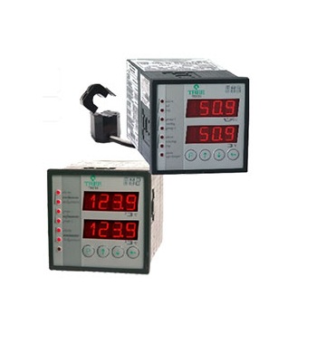
More than just digital thermometers, Treetech’s TM Temperature Monitors form a complete Temperature Monitoring system for transformers and reactors immersed in oil. Designed as a modular system, it can be used in simple, low cost applications, as well as in complete monitoring systems. The system is comprised of modules TM1and TM2:
• TM1, monitors the temperature of the oil and one winding. The device is equipped with:
– Configurable input for one 4-lead RTD sensor, for oil temperature, or two 3-leadsensors- redundant reading of oil temperature1) or simple reading for oil temperature and one additional temperature (e.g.: ambient or LTC);
– One load current measuring input, for calculating temperature of the winding.
• TM2, applied ascomplement to TM1, monitors the temperature of one or two additional windings. It is equipped with:
– Input for connection of additional RTD sensors, user configurable for one 4-lead sensor, or two 3-lead sensors, allowing measurement of one or two additional temperatures (for example, bottom oil, LTC, ambient temperature or others);
– Two current measuring inputs, for calculating the temperature of two additional windings.
In addition to these basic functions, a range of optional features are available in monitors TM1and TM2, such as, for instance, pre- cooling. See Optional Features further ahead.
Main Features:
• IEDs (Intelligent Electronic Devices) designed specifically for substation yard conditions and suited for integration to supervision or monitoring systems by way of ports RS485 and RS232 (Modbus standard, DNP3.0 optional). Fibre optic and Ethernet using appropriate external converter;
• Extended capability to withstand the requirements of the strictest test procedures performed by transformer manufacturers;
• DNP3.0 Protocol (optional) with support for Time-Stamp, capable of storing events, such as: alarms, trips, activation of cooling, etc, with 1ms resolution;
• Extended temperature measurement range, from -55 to 200ºC;
• Inputs for temperature sensors type Pt100W at 0ºC with self-calibration1), ensuring high level of accuracy and stability throughout the entire ambient temperature range;
• Universal AC current measurement inputs, true-rms, for direct connection to the secondary of CT (0 to 10A) or, optionally, connection to external clip-on CT;
• Optional external CT, window type, split-core, avoiding direct connection of the secondary bushing CT to the temperature monitor and reducing the risk of accidental opening of secondary, in addition to allowing installation with the transformer energized;
• High luminosity LED type displays for easy visualization;
• Calculation for forecast of final oil-winding temperature rise for present load;
• Two analog outputs in each monitor for remote temperature readings, with variable and output range programmable (0…1, 0…5, 0…10, 0…20 or 4…20mA);
• Selectable cooling system operation via front panel on Automatic or Manual. Automatic alternation in operation of forced cooling groups in pre-programmed stages, based on their operation times, affording uniform use of fans or pumps;
• Optional Pre-cooling function for reducing insulation loss of life due to elevated loads;by activating cooling groups when user selected load levels are reached. Taking advantage of the large thermal inertia of the oil, the forced cooling systems are activated even before the temperature rises, thus increasing the time required to reach high temperature levels, which would cause accelerated shortening of insulation life cycle. The following parameters are programmed by users:
– Loadingpercentages for individual activation of up to four cooling stages1);
– Hysteresis for shut off of forced cooling stages in case of load reduction1).
• Optional Fan Exercise function for prevention of failures in cooling fans or pumps;keeps fans and / or pumps from remaining inactive for prolonged periods of time in transformers operating under low load conditions or during periods of low ambient temperatures. This avoids axle blocking due to accumulation of dirt, grease dry out or bird nesting. Fans are switched on every day, based on the equipment’s internal clock and depending on selections made by users:
– Hour and minute for start-up of fans and/or pumps;
– Total daily fan and/or pump operation time, from 0 to 999 minutes.
• Self-diagnosis: two micro-controllers with reciprocal supervision for detection of failures, both internal or in sensors;
• Internal clock with settings maintained for 48h in case of failure of power supply. No batteries are used1) – maintenance-free device;
• Total absence of mechanical parts in parameter definition and calibration of devices;
• NO contacts (NC to order) for oil and winding temperature alarms;
• NO contacts (NC to order) for trip due to oil and winding temperature with double safety in activation1) (simultaneous order from two micro-controllers for the operation). Timer adjustable between 0 and 20 minutes with countdown on display;
• NO contact (NC to order) programmable for signalizing any trip condition or LTC temperature differential alarm;
• NC contacts (NO to order) fortriggering up to four forced cooling groups (using TM1 and TM2), with delayed motor start up even in case of loss of control power. The cooling system remains on in case of power loss or internal failure (self-diagnosis);
• NC contact (NO to order) for indication of power loss or failure detected by self-diagnosis.
• Option Temperature Differential for the Load tap Changer
Load Tap Changers are one of the main sources of transformer failure. Measuring the temperature difference between the LTC oil and transformer oil may give an indication of a thermal failure event in the equipment before reaching a level of severity that couldlead to a major failure. Since this difference is subject to the influence of external variables, monitoring is carried out in two different ways, in order to increase efficiency of diagnosis and avoid false alarms:
– Monitoring of instant difference triggers fast response alarms, in case of high intensity defects, even in case of short duration events;
– Monitoring of difference with long term filter triggers alarms sensitive to permanent defects, even in case of low intensity, with longer detection times.
In three-phase transformers using three single-phase tap changers in separate oil chambers the three temperature differences can be monitored separately.
Optional Mass Memory
Non-volatile memory for storage of temperature readings and alarm events. Users select variable groups to store and save to memory. Recording operation can be started by:
– Time interval between storage of readings selected by user; or
– Variation of temperature higherthan anydead band selected by the user, in ºC; or
– Change of state in any output relay (control of cooling, alarms, trips or self-diagnostic).
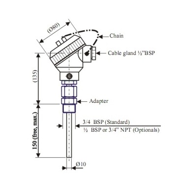
Pt100W at 0ºC Temperature Sensor
The measurement of the top oil temperature in power transformers is usually performed through temperature sensors installed in a “thermal- well” found on the cover of the transformer. Sensors used must be of the Pt100W at 0ºC type. If necessary, Treetech offers a sensor suited for installing in thermal-well. Consult usalso about thermal housings (weather shield) for measurement of ambient temperature.
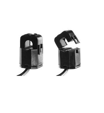
External Clip-on CTs
The use of external clip-on CTs allows the installation of the Temperature Monitors without the direct connection of a bushing CT to the instruments. This reduces the risk of accidentally opening the CT secondary, besides simplifying the installation with the transformer energized.Operation temperature -40 to +85°C.
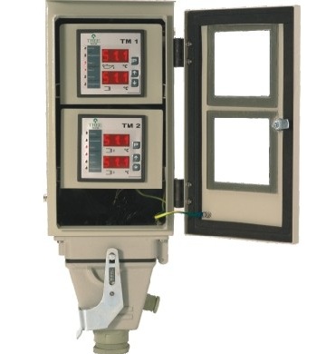
Cubicles
The TM1 and TM2 Temperature Monitors must be installed protected from the weather, and for this reason, they are usually installed inside the transformer’s control panel. In situations where this is not convenient, such as for example in refitting older transformers, the Temperature Monitors can be supplied in easy-to-install weatherproof cubicles.